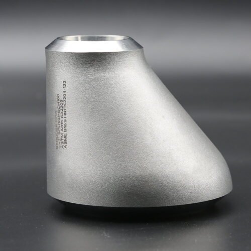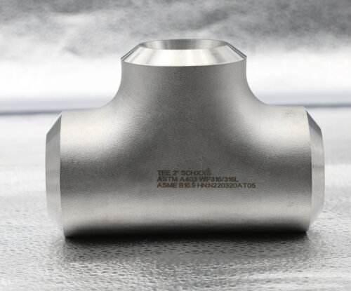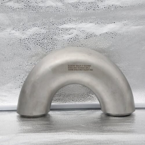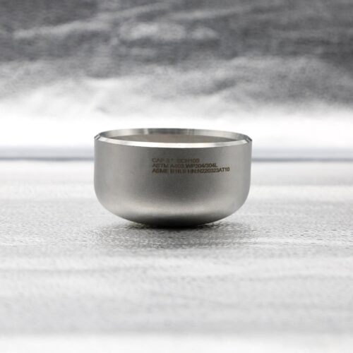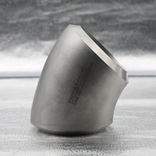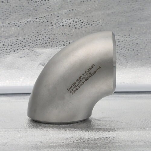
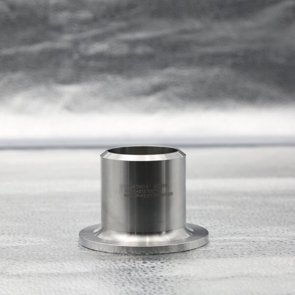
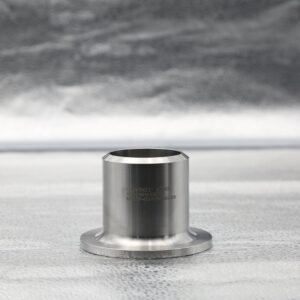
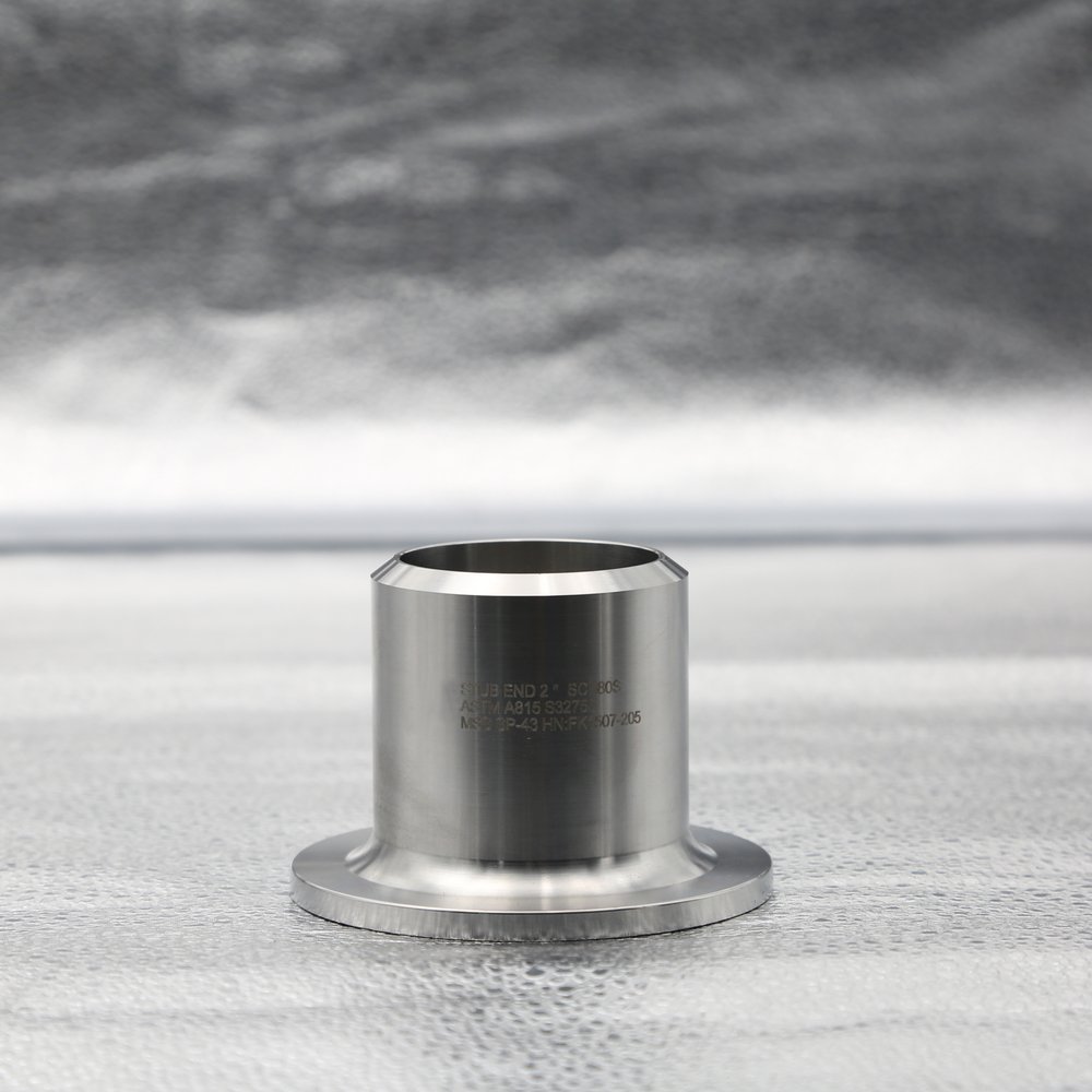
A lap joint stub end is a butt weld fitting used with a loose lap joint flange to form a detachable flanged connection. Its lap provides the gasket sealing face, while the backing flange transfers the bolt load. This product guide covers stainless steel, duplex, super duplex and nickel alloy options, long and short patterns, and ASME B16.9 dimensions from NPS ½ to 24 (DN15–DN600) — the photographed example is ASTM A815 UNS S32750, NPS 2 Sch 80S.
NPS ½”–24″ (DN15–DN600) · Long & short pattern · Sch 5S – XXS (subject to confirmation)
Specifications · Materials · Patterns · Dimensions · Request a quote · FAQ
Lap Joint Stub End Specifications
| Product type | Butt weld lap joint stub end for use with a compatible backing flange |
|---|---|
| Patterns | Long pattern or short pattern; specify at ordering |
| Dimensional reference | ASME B16.9; MSS SP-43 requirements may be specified separately, subject to confirmation |
| Size reference | NPS ½–24 (DN15–DN600), as shown in the ASME B16.9 stub end table; supply availability requires confirmation |
| Wall thickness | Specify schedule and schedule standard or actual thickness. Catalogue range: Sch 5S through XXS, subject to grade, size and manufacturing confirmation |
| Materials | Austenitic, duplex and super duplex stainless steels; selected nickel alloys |
| Welding end | End preparation to the specified ASME B16.9 requirements or agreed purchase drawing |
| Lap and gasket face | For ASME B16.9 standard geometry, lap thickness is at least nominal pipe wall thickness; gasket finish and back-face compatibility follow Table 6.1-9 notes |
Stainless Steel, Duplex and Nickel Alloy Material Options
Specify both the fitting material standard and the exact grade. A dimensional standard such as ASME B16.9 does not replace a material specification. The grades below are selection references; confirm the applicable specification, manufacturing class, heat treatment and availability in the quotation.
| Material family | Common grades / UNS | Material specification to confirm |
|---|---|---|
| Austenitic stainless steel | 304L, 316L, 317L, 321, 904L | ASTM A403, exact grade and class |
| Duplex stainless steel | 2205: S32205 or S31803; specify the exact UNS | ASTM A815, exact grade and class |
| Super duplex stainless steel | 2507: S32750; S32760 | ASTM A815, exact grade and class |
| Super austenitic stainless steel | S31254; N08367 | Applicable grade-specific fitting specification |
| Nickel alloys | Alloy 625: N06625; Alloy 825: N08825; Alloy 400: N04400; C-22: N06022; C-276: N10276 | ASTM B366, applicable grade and class |
Use fluid composition, chloride concentration, operating temperature and corrosion history to assess material suitability. No single stainless steel or nickel alloy is suitable for every acid, seawater or high-temperature service.
Long Pattern vs Short Pattern Stub Ends
Choose the pattern by assembly geometry and weld access. Short patterns reduce overall length, while long patterns provide more barrel length. Check the mating flange bore and radius, lap dimensions, facing and available welding space. ASME B16.9 requires the purchaser to specify the pattern; certain flange sizes and classes require an agreed increase in stub end length.
Why Use a Stub End with a Lap Joint Flange?
- Easier bolt alignment: the loose flange can rotate to align bolt holes before tightening.
- Maintenance access: the bolted joint supports disassembly for inspection or cleaning when the piping layout permits.
- Material cost control: a corrosion-resistant wetted stub end can be paired with a carbon steel backing flange where the design and external environment permit.
The backing flange generally remains outside the process fluid, but its strength, external corrosion resistance and compatibility still require evaluation.
Lap Joint Stub End Dimensions (mm)
Dimensions per ASME B16.9-2024 Table 6.1-9. F = overall length, R = fillet radius, G = lap diameter. Use the tolerances and notes in the specified edition of the standard. Barrel OD limits are not the nominal pipe outside diameter.
| DN | NPS | Barrel OD max / min | F long pattern | F short pattern | R | G |
|---|---|---|---|---|---|---|
| 15 | ½” | 22.8 / 20.5 | 76 | 51 | 3 | 35 |
| 20 | ¾” | 28.1 / 25.9 | 76 | 51 | 3 | 43 |
| 25 | 1″ | 35.0 / 32.6 | 102 | 51 | 3 | 51 |
| 32 | 1¼” | 43.6 / 41.4 | 102 | 51 | 5 | 64 |
| 40 | 1½” | 49.9 / 47.5 | 102 | 51 | 6 | 73 |
| 50 | 2″ | 62.4 / 59.5 | 152 | 64 | 8 | 92 |
| 65 | 2½” | 75.3 / 72.2 | 152 | 64 | 8 | 105 |
| 80 | 3″ | 91.3 / 88.1 | 152 | 64 | 10 | 127 |
| 90 | 3½” | 104.0 / 100.8 | 152 | 76 | 10 | 140 |
| 100 | 4″ | 116.7 / 113.5 | 152 | 76 | 11 | 157 |
| 125 | 5″ | 144.3 / 140.5 | 203 | 76 | 11 | 186 |
| 150 | 6″ | 171.3 / 167.5 | 203 | 89 | 13 | 216 |
| 200 | 8″ | 222.1 / 218.3 | 203 | 102 | 13 | 270 |
| 250 | 10″ | 277.2 / 272.3 | 254 | 127 | 13 | 324 |
| 300 | 12″ | 328.0 / 323.1 | 254 | 152 | 13 | 381 |
| 350 | 14″ | 359.9 / 354.8 | 305 | 152 | 13 | 413 |
| 400 | 16″ | 411.0 / 405.6 | 305 | 152 | 13 | 470 |
| 450 | 18″ | 462 / 456 | 305 | 152 | 13 | 533 |
| 500 | 20″ | 514 / 507 | 305 | 152 | 13 | 584 |
| 550 | 22″ | 565 / 558 | 305 | 152 | 13 | 641 |
| 600 | 24″ | 616 / 609 | 305 | 152 | 13 | 692 |
Specify actual wall thickness or the applicable schedule series. ASME B36.19 stainless steel schedules and ASME B36.10 schedules must not be treated as interchangeable. Confirm weld clearance, flange bore, fillet radius and facing before ordering. Special lengths and facings require agreement. Reference: ASME B16.9-2024, Table 6.1-9, printed page 20.
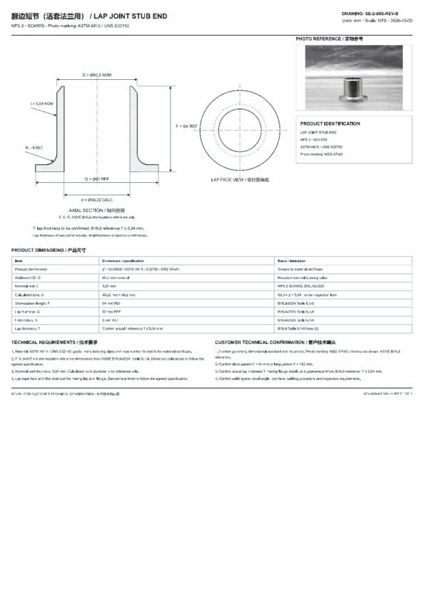
Engineering Drawing — Lap Joint Stub End (ASME B16.9)
The REV B drawing shows the lap joint stub end geometry: barrel outside diameter D, overall length F, fillet radius R, lap diameter G and lap thickness T, with axial section and lap face view. The example dimensioned is NPS 2 Sch 80S, ASTM A815 UNS S32750, MSS SP-43 — the same fitting shown in the photograph: D = 60.3 mm, F = 64 mm (short pattern), R = 8 mm, G = 92 mm, t = 5.54 mm nominal.
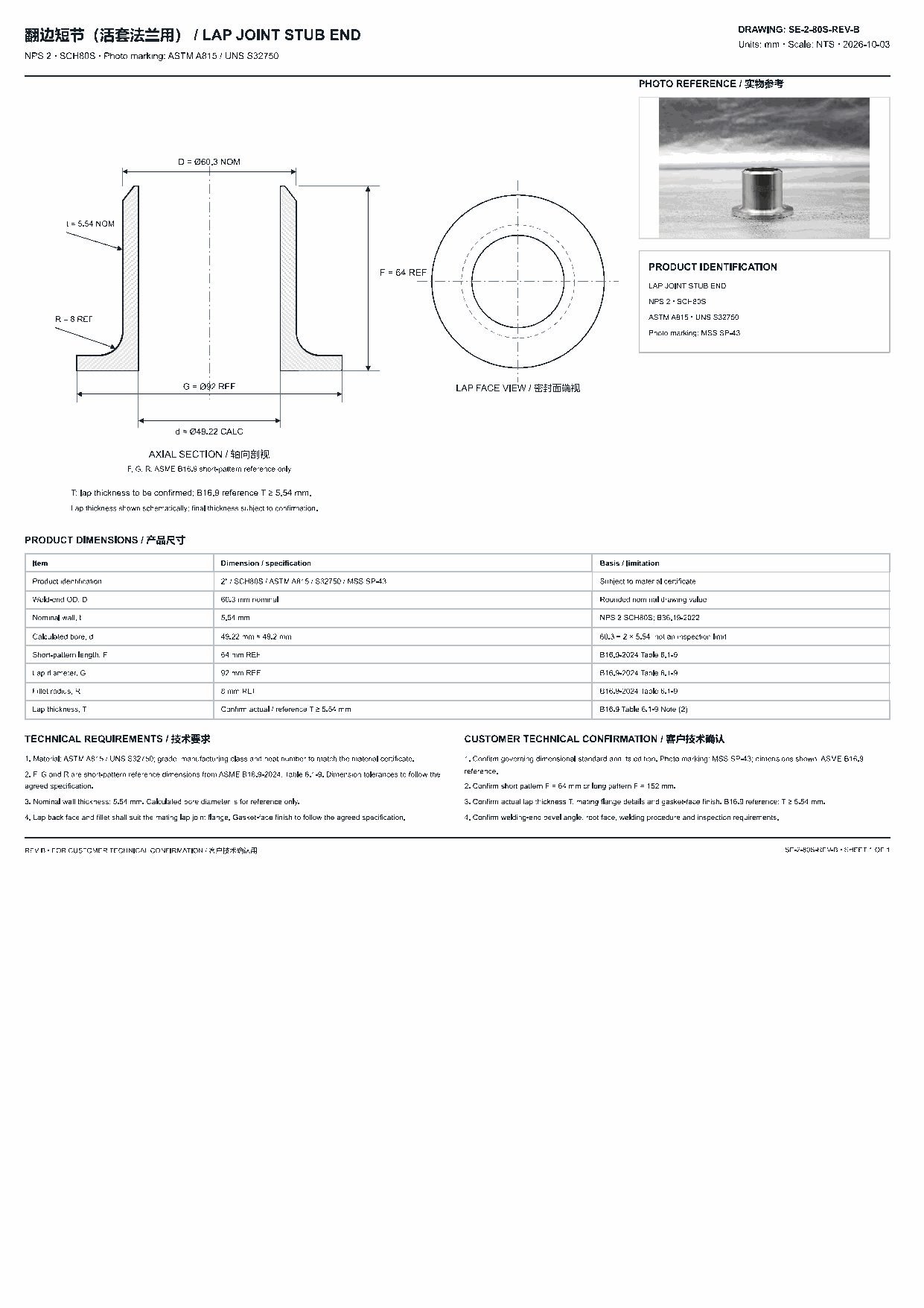
F, R and G are ASME B16.9 reference dimensions; order dimension values follow the ordered pattern and schedule. A PDF copy is available via the Drawing Download button above.
Applications and Service Selection
Lap joint assemblies are considered for chemical processing, water treatment, desalination, offshore piping, pulp and paper, and other systems requiring detachable connections. Food and pharmaceutical applications require separate evaluation of cleanability, internal geometry, surface finish and the applicable hygienic requirements.
Inspection, Marking and Documentation
Specify the inspection and document requirements in the purchase order, including material certification, traceability, dimensional inspection, surface condition and any additional testing. Additional PMI, corrosion testing or nondestructive examination must be agreed where required; they are not implied by this product description.
ASME B16.9 marking covers manufacturer identification, material grade, wall thickness or schedule, nominal size and conformity marking, with exceptions for fittings too small for complete marking. Confirm the full grade and manufacturing class against the applicable material specification.
Request a Lap Joint Stub End Quotation
Send these details so the product and mating flange can be checked together:
- Material specification, exact grade or UNS, and required manufacturing class.
- Nominal size, schedule standard and schedule number, or actual wall thickness.
- Long or short pattern, dimensional standard and edition, or an approved drawing.
- Mating flange standard, class, bore and facing; gasket requirements.
- Quantity, destination, required delivery date and service conditions.
- Required certification, inspection, testing and marking.
Example enquiry: Lap joint stub end, ASTM A403 WP316L (class to be specified), NPS 2, Sch 10S to ASME B36.19, short pattern to ASME B16.9-2024, for a compatible ASME B16.5 Class 150 lap joint flange, quantity 50. Confirm facing, certification and delivery in the quotation.
Lap Joint Stub End FAQ
What is a lap joint stub end?
A lap joint stub end is a butt weld pipe fitting with a flared lap at one end. The welding end joins the pipe; the lap provides the gasket contact surface and is supported by a loose lap joint flange.
What is the difference between a stub end and a lap joint flange?
The stub end forms part of the fluid-containing piping and provides the sealing face. The lap joint flange sits behind the lap and transfers bolt load. The two components are selected together; the flange alone does not replace the stub end.
How do long pattern and short pattern stub ends differ?
The principal dimensional difference is overall length F. Specify the pattern explicitly. Flange size and class can require additional length to keep the flange clear of the weld; special facing can also require additional lap thickness.
Are ASME B16.9 and MSS SP-43 interchangeable?
Do not assume interchangeability. Specify the governing standard and edition, pattern, material and wall thickness, then verify the dimensional and service requirements for the complete assembly. Compliance with one standard does not establish compliance with the other.
Which materials should I consider?
Common material options include 304L and 316L stainless steel, duplex S32205/S31803, super duplex S32750/S32760 and nickel alloys such as N06625 and N10276. Selection depends on fluid chemistry, temperature, pressure, corrosion conditions and the governing piping code. Confirm availability for the exact grade, size and specification.
Does a stub end have the same pressure class as its flange?
A flange class is not a standalone pressure rating for the stub end. Evaluate the complete joint using the material, wall thickness, design temperature, flange, gasket, bolts and applicable piping code. ASME B16.9 design proof-test exemption for lap joint stub ends does not waive other applicable inspection or system test requirements.
What information is needed for a quotation?
Provide the material specification and grade or UNS, NPS/DN, schedule or wall thickness, long or short pattern, dimensional standard and edition, mating flange class and facing, quantity, service conditions and required inspection documents.
Technical Reference
Dimensional and assembly notes are based on ASME B16.9-2024, section 6.2.3 and Table 6.1-9. Marking references are in section 4; the design proof-test exemption is in Table 9.2.1-1. The purchase order must identify the governing standard edition and project requirements.