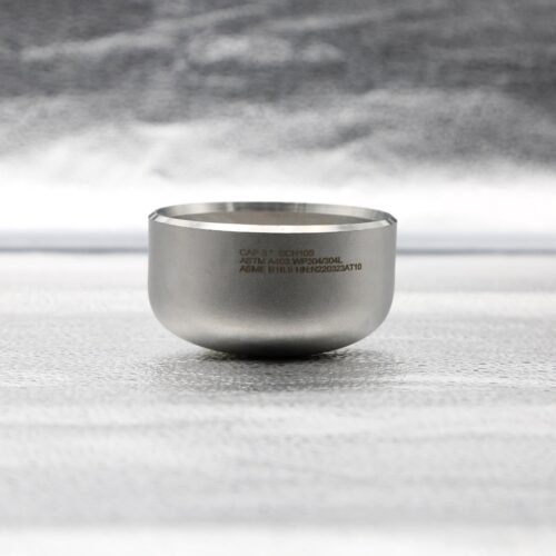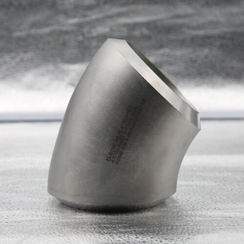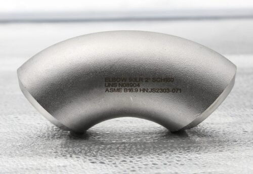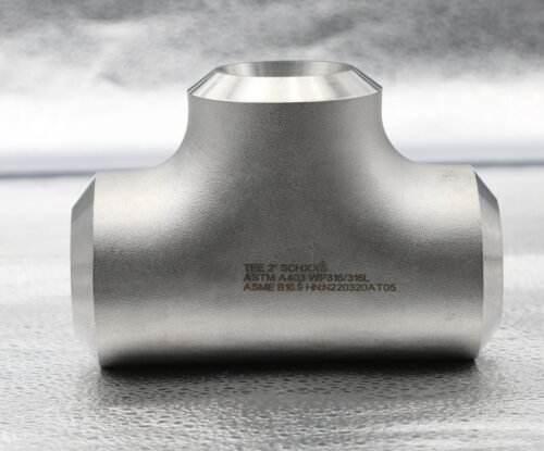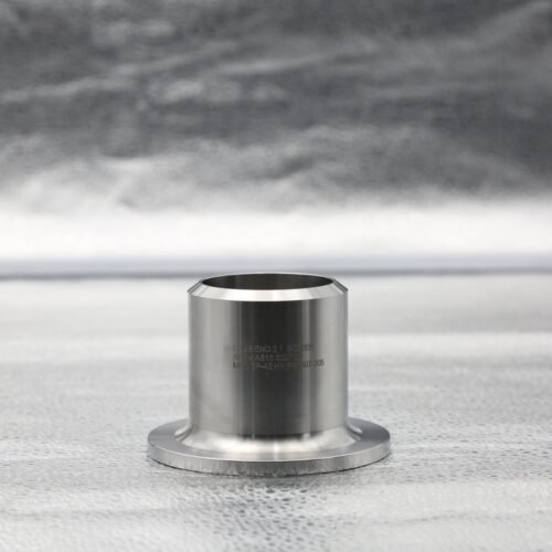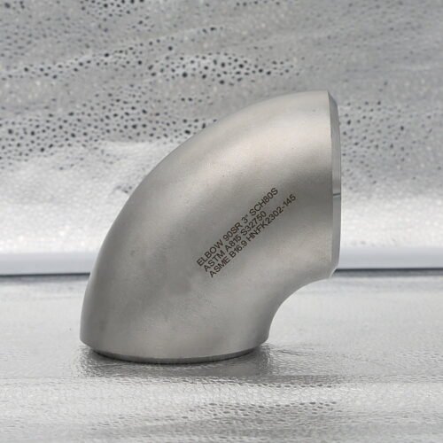
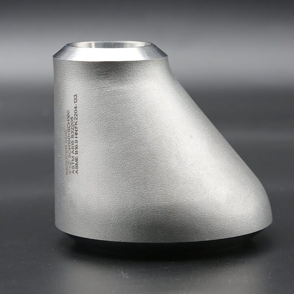
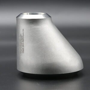
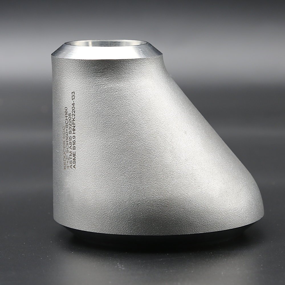
An eccentric reducer is a butt weld pipe fitting that connects two different pipe sizes with offset centerlines, keeping one side of the transition straight. Made to ASME B16.9 in stainless steel, duplex (S32205 / S31803), super duplex (S32750 / S32760), super austenitic and nickel alloy grades — the photographed example carries ASTM A403 WP316/316L laser marking.
Seamless up to NPS 24 (DN600) · Welded up to NPS 40 (DN1000) · Small ends down to NPS ½ · Sch 5S – XXS
What Is an Eccentric Reducer?
An eccentric reducer is a butt weld pipe fitting that connects two different pipe sizes with offset centerlines, keeping one side of the transition straight. It is used where the piping layout requires top or bottom alignment, including selected horizontal pump suction and process lines.
Wenzhou Xinzhe Tech offers eccentric reducers in stainless steel, duplex, super duplex, super austenitic and nickel alloy grades. Specify the large and small end sizes, wall thickness at each end, material grade and dimensional standard to obtain a project-specific quotation.
For an ASME B16.9 order, specify the applicable standard edition and material specification together. ASME B16.9 defines fitting requirements, while the material specification defines the applicable grade, manufacturing class and material requirements. Compliance with one dimensional standard does not establish compliance with every other listed standard.
Eccentric Reducer Specifications
| Product | Eccentric reducer (ECC reducer), butt weld pipe fitting |
|---|---|
| Manufacturing options | Seamless or welded construction; specify the required material specification and manufacturing class |
| Catalogue size range | Seamless sizes up to NPS 24; welded sizes up to NPS 40. Small ends down to NPS ½, depending on the size combination. Confirm the exact large × small end pair and manufacturing availability |
| Wall thickness | Catalogue options from Sch 5S through XXS, subject to size, material and schedule standard. Specify both ends; not every schedule exists for every size |
| Dimensional standard | ASME B16.9, edition as specified in the purchase order |
| Other project standards | MSS SP-43, EN 10253-4, GB/T 12459 or other requested specifications require scope and supply confirmation |
| Material specifications | Typically ASTM A403 for austenitic stainless grades, ASTM A815 for duplex / super duplex grades and ASTM B366 for applicable nickel alloy grades |
| Weld ends | End preparation according to the governing standard and ordered wall thickness; confirm any special welding requirements |
| Documentation | Request EN 10204 Type 3.1 inspection certification, heat traceability and any additional inspection or testing in the purchase order |
Note: These are catalogue ranges, not a guarantee that every size, schedule, material and manufacturing route is available in every combination. Confirm the exact large × small end pair, both end wall thicknesses and the manufacturing route when requesting a quotation. Sizes beyond the standard dimension tables require an agreed drawing and acceptance basis.
Material Grades for Stainless Steel, Duplex and Nickel Alloy Reducers
Select the material for the actual fluid composition, operating temperature, pressure and corrosion conditions. Commercial grade names help identify options, but the purchase specification should state the exact grade or UNS and the applicable fitting specification.
| Material family | Grade / UNS options |
|---|---|
| Austenitic stainless steel | 304 / 304L / 304H; 316 / 316L / 316H / 316Ti; 317L; 310S; 321 / 321H; 904L |
| Duplex stainless steel | 2205: UNS S32205 or S31803; specify the exact UNS rather than treating the two as automatically interchangeable |
| Super duplex stainless steel | 2507: UNS S32750; UNS S32760 |
| Super austenitic stainless steel | UNS S31254 (254 SMO); UNS N08367 (AL-6XN) |
| Nickel and nickel-copper alloys | Alloy 400: N04400; Nickel 200: N02200; Nickel 201: N02201 |
| Selected high-performance alloys | N06600; N06601; Alloy 625: N06625; C-22: N06022; C-276: N10276; B-2: N10665; B-3: N10675 |
| Selected iron-nickel-chromium alloys | Alloy 20: N08020; N08800; N08810; N08811; Alloy 825: N08825 |
Material specifications: typically ASTM A403 for austenitic stainless grades, ASTM A815 for duplex / super duplex grades and ASTM B366 for applicable nickel alloy grades. Confirm the applicable specification and manufacturing class for each grade, particularly specialty austenitic and high-alloy materials. Grade selection alone does not establish suitability for every acid, chloride environment or high-temperature application.
Why Choose an Eccentric Reducer?
- Pipe alignment: the offset transition allows one side to remain aligned between different pipe sizes.
- Pump suction layout: suitable orientation can reduce the risk of a local air pocket in a horizontal liquid suction line.
- Drainage and bottom alignment: a selected flat-on-bottom arrangement can support drainage or maintain bottom alignment where required by the piping design.
- Layout flexibility: eccentric geometry can accommodate elevation constraints without keeping both pipe centerlines on the same axis.
Flow performance depends on the complete piping layout, reduction ratio and operating conditions. An eccentric reducer does not by itself guarantee freedom from cavitation, solids deposition or pressure loss.
Flat-on-Top vs Flat-on-Bottom Installation
| Orientation | Typical design purpose | What to verify |
|---|---|---|
| Flat on top (FOT) | Often used in horizontal liquid pump suction piping to avoid a local high point that can trap air | Suction-line slope, approach geometry, venting, inlet flow conditions and the pump supplier’s requirements |
| Flat on bottom (FOB) | Used where bottom alignment, drainage or a specified invert elevation is required | Gas-pocket risk, solids transport, drainage, pipe supports and the approved piping layout |
Follow the approved piping design and pump manufacturer’s installation guidance. Flat-on-bottom is not a universal rule for slurry service; deposition also depends on flow velocity, solids properties and the overall line geometry. Cavitation assessment additionally requires the available NPSH, pump requirements, temperature and suction losses.
Technical context: KSB recommends eccentric reducers in horizontal suction lines to help avoid air pockets. See the pump installation manual for the specific arrangement.
Eccentric Reducer vs Concentric Reducer
| Feature | Eccentric reducer | Concentric reducer |
|---|---|---|
| Pipe centerlines | Offset | Coincident |
| Transition alignment | One side can remain straight / aligned | Symmetrical about a common centerline |
| Typical selection reason | Control top or bottom alignment; address local air-pocket or drainage concerns | Maintain a common pipe axis where the layout and service permit |
| Selection check | Orientation, venting, drainage and pump inlet requirements | Orientation, venting, drainage and pump inlet requirements |
Neither type is universally preferred for every liquid, gas or steam line. Select the geometry from the service conditions and piping layout rather than from fluid category alone.
ASME B16.9 Eccentric Reducer Dimensions
The sample below uses the SI values in ASME B16.9-2024, Table 6.1-11. H is the end-to-end length; the outside diameters are the nominal values at the welding ends. Apply the tolerances in the specified standard edition.
| NPS, large × small | Large-end OD (mm) | Small-end OD (mm) | End-to-end H (mm) |
|---|---|---|---|
| 2 × 1 | 60.3 | 33.4 | 76 |
| 6 × 4 | 168.3 | 114.3 | 140 |
| 14 × 12 | 355.6 | 323.8 | 330 |
| 20 × 16 | 508.0 | 406.4 | 508 |
For a standard size pair, Table 6.1-11 does not assign different H values by schedule. Special lengths require agreement. Use either the SI or US Customary values from the standard consistently; do not replace standard SI values with exact conversions from inches.
Specify large-end wall thickness T1 and small-end wall thickness T2 separately. The same schedule number can correspond to different thicknesses at the two sizes. ASME B36.19 stainless steel schedules and ASME B36.10 schedules are not automatically interchangeable.
Drawing support: request a size-specific drawing showing end diameters, H, end wall thicknesses, eccentric orientation and weld preparation before approval. For special bore or flow-path requirements, include them in the purchase specification.
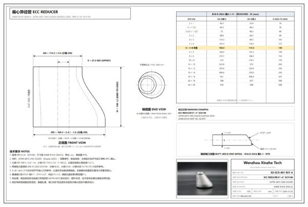
Engineering Drawing — Eccentric Reducer (ASME B16.9)
The REV A drawing shows the eccentric reducer geometry with the flat side left: large-end OD 168.3 ±2.4 / −1.6 mm, small-end OD 114.3 ±1.6 mm, end-to-end H = 140 ±2 mm and offset E = 27.0 mm (reference) for the dimensioned NPS 6 × 4 SCH160 example, with the butt-weld end detail per ASME B16.9-2024 Table 8-1 (bevel 37.5° ±2.5°, root face 1.5 ±1.0 mm) and the B16.9-2024 Table 6.1-11 SI dimension table. Marking example: ECC REDUCER 6″×4″ SCH160 · ASTM A815 UNS S32205 (DUPLEX 2205), with heat number for MTC traceability.
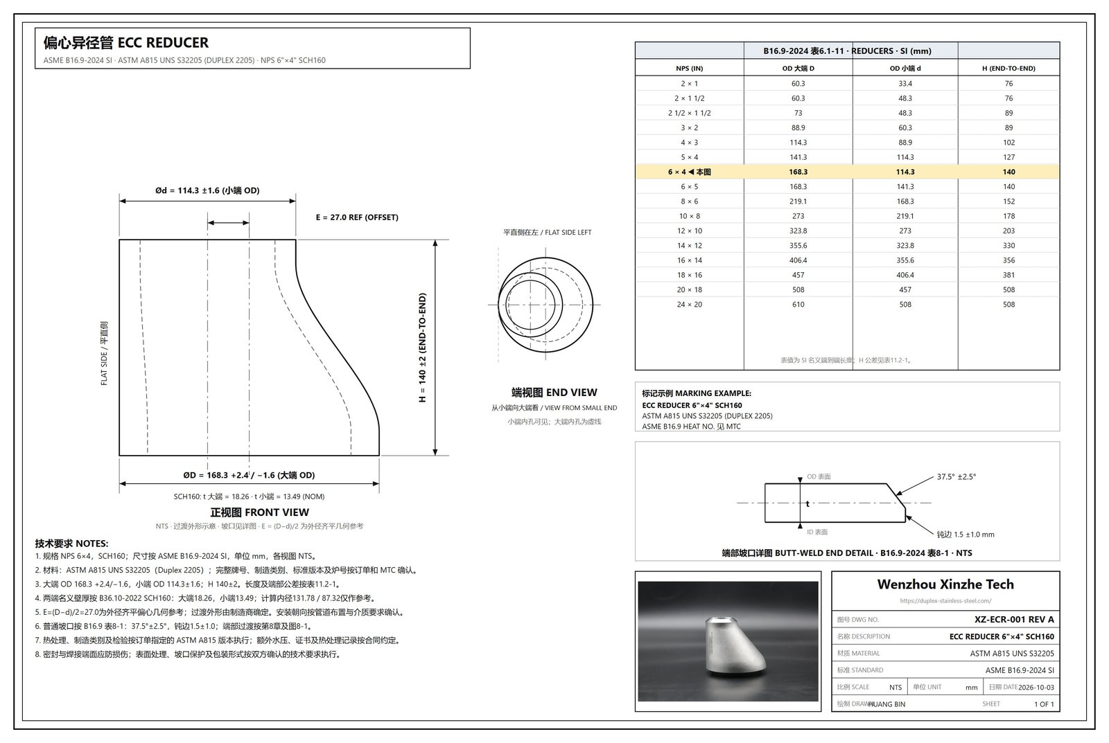
The drawing is a review reference; order values follow the ordered size pair, schedule standard and material specification. Use the final agreed manufacturing drawing and material documentation for order acceptance. A PDF copy is available via the Drawing Download button above.
Manufacturing, Inspection and Certification
Seamless and welded construction must meet the selected material specification and ordered manufacturing class. Forming, heat treatment, weld examination and surface treatment depend on the grade and applicable requirements; agree the delivery condition in the quotation.
- Specify dimensional and visual inspection, end thickness checks and material traceability.
- Request EN 10204 Type 3.1 certification and define the required chemical, mechanical and heat-treatment records.
- Specify PMI, PT, RT, UT, corrosion testing or ferrite assessment where the material specification or project requires them; define the method, extent and acceptance criteria.
- Use ASTM A262 or ASTM A923 only where applicable to the grade and project requirement; do not apply one test to every material family.
ASME B16.9 section 10 does not require a hydrostatic production test of each wrought fitting. Design qualification, material-standard testing, agreed purchase inspections and the piping system pressure test are separate requirements.
Marking should follow the applicable dimensional and material standards, including manufacturer identification, material grade, wall thickness and size as required. Agree any additional heat-number, project or ECC identification requirements.
Applications and Material Selection
Eccentric reducers are used in oil and gas facilities, chemical and petrochemical plants, water treatment, desalination, power generation, pulp and paper and other process piping. Duplex, super duplex and selected nickel alloys can be considered where the service requires their specific corrosion or strength characteristics.
Food, beverage and pharmaceutical service requires additional consideration of internal finish, cleanability, weld quality and hygienic design. A standard industrial butt weld reducer is not automatically a hygienic fitting.
Request an Eccentric Reducer Quotation
Send Wenzhou Xinzhe Tech the following information for pricing and technical confirmation:
- Large × small end size, for example NPS 6 × 4.
- Schedule standard and schedule at each end, or actual T1 and T2 wall thickness.
- Material specification, exact grade or UNS, manufacturing class and required delivery condition.
- Dimensional standard and edition; any special H, bore, weld-end or drawing requirements.
- Seamless or welded construction, quantity, destination and required delivery date.
- Design conditions and certification, inspection, testing and marking requirements.
Example enquiry: Eccentric reducer, NPS 6 × 4, ASTM A815 UNS S32205 (exact grade designation and manufacturing class to be specified), seamless construction, ASME B16.9-2024, large and small ends Sch 160 to ASME B36.10, quantity 20, EN 10204 Type 3.1 certification required. Confirm end thicknesses, heat treatment, examination requirements and delivery in the quotation.
Eccentric Reducer FAQ
What is an eccentric reducer used for?
An eccentric reducer connects different pipe sizes with offset centerlines. It is selected where top or bottom alignment matters, including selected horizontal pump suction lines and process piping.
How does an eccentric reducer differ from a concentric reducer?
An eccentric reducer has offset centerlines and one aligned side. A concentric reducer shares a common centerline at both ends. Choose the geometry according to the piping layout, venting, drainage and equipment requirements.
Should an eccentric reducer be installed flat on top or flat on bottom?
Flat-on-top is often used in horizontal liquid pump suction lines to avoid a local air pocket. Flat-on-bottom may be selected for bottom alignment or drainage. Follow the approved layout and pump manufacturer’s guidance; neither orientation is correct for every application.
Does an eccentric reducer prevent pump cavitation?
Correct geometry and orientation can reduce local air-pocket risk, but they do not guarantee that cavitation will be avoided. Check available NPSH, pump requirements, liquid temperature, suction losses and the complete inlet layout.
What materials can be specified?
Options include austenitic stainless grades such as 304L and 316L, duplex S32205/S31803, super duplex S32750/S32760, super austenitic grades and selected nickel alloys such as N06625 and N10276. Specify the exact grade, material specification and manufacturing class.
What sizes and schedules can be quoted?
Catalogue options include seamless sizes up to NPS 24 and welded sizes up to NPS 40, with small ends down to NPS ½ for applicable size pairs. Wall options extend from Sch 5S through XXS, subject to the size, material and schedule standard. Confirm the exact combination in the quotation.
Does the same schedule mean the same wall thickness at both ends?
No. Schedule thickness depends on nominal pipe size and the applicable schedule standard. Specify or confirm T1 at the large end and T2 at the small end.
Are material certificates and additional tests available?
Request EN 10204 Type 3.1 certification and any additional PMI, nondestructive examination or corrosion testing with the enquiry. The quotation and purchase order should define availability, test methods, extent and acceptance criteria.
Technical References
Dimensional data: ASME B16.9-2024, Table 6.1-11, printed pages 23–24. Weld preparation: section 8 and Table 8-1. Production testing: section 10. Apply the purchase order edition.
Pump-suction installation context: KSB centrifugal pump lexicon — fittings and formation of air pockets. The specific arrangement follows the approved piping design and the pump manufacturer’s installation manual.