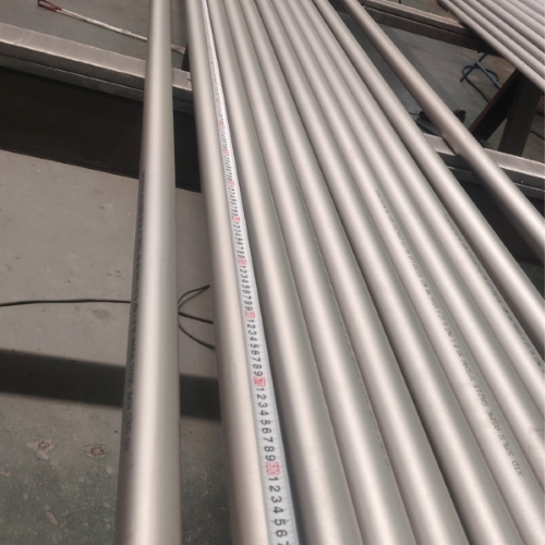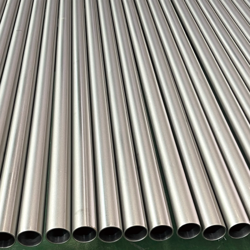

What Is a Seamless Stainless Steel U-Tube?
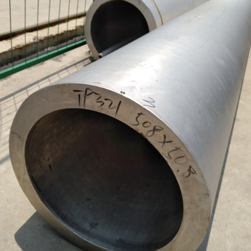
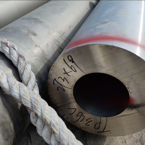
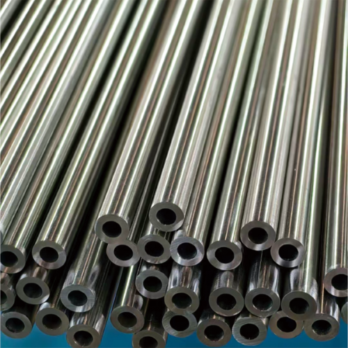
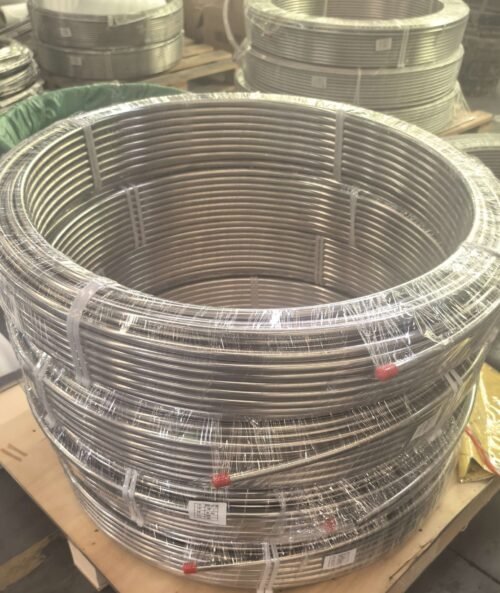
Seamless Stainless Steel U-tubes are specialized heat-exchanger components made by cold-bending high-quality seamless straight tubes into a precise “U” configuration. Manufactured from a single solid billet without any longitudinal weld seam, they provide unmatched structural integrity for high-pressure and high-temperature thermal management systems.
The U-bend design is a mechanical necessity for shell-and-tube heat exchangers: it allows free thermal expansion and contraction of the tube bundle, eliminates the need for expansion joints, reduces the equipment footprint, and enables multi-pass fluid flow to maximize heat-transfer efficiency.
International compliance and technical standards:
- ASTM A213 / ASME SA213: seamless ferritic and austenitic alloy-steel boiler, superheater and heat-exchanger tubes.
- ASTM A789 / ASME SA789: seamless duplex stainless steel tubing for general service.
- ASTM B163: seamless nickel and nickel-alloy condenser and heat-exchanger tubing.
- ASTM B161 / B167 / B668: nickel, Ni-Cr-Fe and UNS N08028 alloy tubing.
- EN 10216-5: European technical delivery conditions for stainless steel tubes.
Key Features and Engineering Advantages
- Optimized Thermal Management: the multi-pass U-shape increases effective surface area inside a compact shell, enhancing overall thermal efficiency.
- Unrivaled Pressure Resistance: seamless construction eliminates weld-related weak points, allowing higher safe working pressures.
- Corrosion Resistance: austenitic and duplex chemistries resist oxidation, pitting and stress corrosion cracking (SCC).
- Space-Saving Design: U-tube bundles offer a reduced footprint versus straight-tube configurations — ideal for offshore platforms and compact plants.
- Enhanced Fatigue Life: no weld seam and no stress concentration ensure durability under vibration and thermal cycling.
Product Specifications and Data
Chemical Composition
Chemical composition is grade-specific. Acceptance limits shall follow the ordered grade and governing material specification, and heat analysis shall be reported on the mill test certificate. U-bending does not define a separate chemical composition.
Size Tolerance Chart
Straight-tube permissible variations before bending, per ASTM A213/A213M for hot-finished (HFD) and cold-finished (CFD) tubes:
| Standard | OD (D), mm | OD Tolerance (mm) | Thickness (S), mm | Thickness Tolerance | Length | Length Tolerance |
|---|---|---|---|---|---|---|
| A213 HFD | D≤100 | +0.4 / -0.8 | D<100, S≤2.4 | +40% / 0 | HFD, all size | +5 / 0 |
| A213 HFD | D≤100 | +0.4 / -1.2 | D<100, 2.4≤S≤3.8 | +35% / 0 | HFD, all size | +5 / 0 |
| A213 HFD | D≤100 | +0.4 / -1.6 | D<100, 3.8≤S≤4.6 | +33% / 0 | HFD, all size | +5 / 0 |
| A213 HFD | 100 | +0.4 / -1.2 | D>100, 2.4≤S≤3.8 | +35% / 0 | HFD, all size | +5 / 0 |
| A213 HFD | 200 | +0.4 / -1.6 | D>100, 3.8≤S≤4.6 | +33% / 0 | HFD, all size | +5 / 0 |
| A213 HFD | 200 | +0.4 / -1.6 | D>100, S>4.6 | +28% / 0 | HFD, all size | +5 / 0 |
| A213 CFD | D<25 | ±0.10 | D≤38.1 | +20% / 0 | CFD, D<50.8 | +3 / 0 |
| A213 CFD | 25≤D≤40 | ±0.15 | D≤38.1 | +20% / 0 | CFD, D<50.8 | +3 / 0 |
| A213 CFD | 40 | ±0.20 | D≤38.1 | +20% / 0 | CFD, D<50.8 | +3 / 0 |
| A213 CFD | 50≤D<65 | ±0.25 | D≤38.1 | +20% / 0 | CFD, D<50.8 | +3 / 0 |
| A213 CFD | 65≤D<75 | ±0.30 | D>38.1 | +22% / 0 | CFD, D≥50.8 | +5 / 0 |
| A213 CFD | 75≤D≤100 | ±0.38 | D>38.1 | +22% / 0 | CFD, D≥50.8 | +5 / 0 |
| A213 CFD | 100 | +0.38 / -0.64 | D>38.1 | +22% / 0 | CFD, D≥50.8 | +5 / 0 |
| A213 CFD | 200 | +0.38 / -1.14 | D>38.1 | +22% / 0 | CFD, D≥50.8 | +5 / 0 |
U-Bend Fabrication Parameters
- Bend radius (R): produced to the radius ordered, with strict control of wall-thinning at the bend.
- Leg length and pitch: 100% dimensional verification of leg length and pitch after bending.
- Post-bend stress relieving: heat treatment applied to the U-bend area to relieve residual bending stresses.
- Minimum bend radius: agreed in the order according to the tube size and exchanger design (TEMA-type requirements on request).
Length Tolerance
- For tubes ordered to a specific cut length: cold-finished (CFD) +3 mm / −0 mm; hot-finished (HFD) +5 mm / −0 mm.
Note: dimensional data above are summarized from ASTM A213/A213M and ASTM A1016/A1016M general requirements. The full and most current specification document must always be consulted for official design and procurement purposes.
Common Industrial Applications
Seamless U-tubes are the standard solution where thermal expansion must be absorbed inside the exchanger:
Power & Nuclear
Critical for condensers, feed-water heaters and nuclear steam generators.
Chemical Processing
High-pressure heat exchangers for corrosive fluid processing.
Marine Engineering
Compact ship condensers and saltwater cooling systems.
HVAC & Energy
High-efficiency chillers and industrial heat pumps.
Frequently Asked Questions
What sizes are available for ASTM A213 stainless steel U-tube?
The overall range is OD 6–257 mm; WT 0.5–35 mm. Requirements outside this range are reviewed against mill capability on request.
Which specification governs ASTM A213 stainless steel U-tube?
ASTM A213 / ASME SA213 is the governing specification for ASTM A213 stainless steel U-tube. The edition in force at order time is stated on the quotation and purchase order; chemistry, mechanical properties, heat treatment, dimensions and testing are reported against the ordered standard and material heat.
What inspection documents are provided?
Each order is documented with a mill test certificate stating heat chemistry and mechanical test results. EN 10204 3.1 certification, hydrostatic testing, eddy-current or ultrasonic inspection and PMI are performed when specified in the purchase order.
Ready to Request a Quotation?
For a seamless stainless steel U-tube quotation, send the standard and grade, outside diameter, wall thickness, bend radius (R), leg length, pitch, quantity and required inspection documents. We will confirm the available size combination and delivery terms in the quotation.